Parallel branches
Each tray connects to both headers. Coolant can reach any tray without passing through another.
The manifold distributes coolant to each tray and monitors flow, temperature and pressure at the rack.
Explore the standalone valveThree parallel paths
Coolant splits between three trays. It picks up heat in the cold plates and rejoins the return header.
The headers connect to each tray through paired ports. Integrated valves control flow, and sensors provide the readings used for thermal energy monitoring.
Need the valve on its own? Explore the Automatic Flow Valve
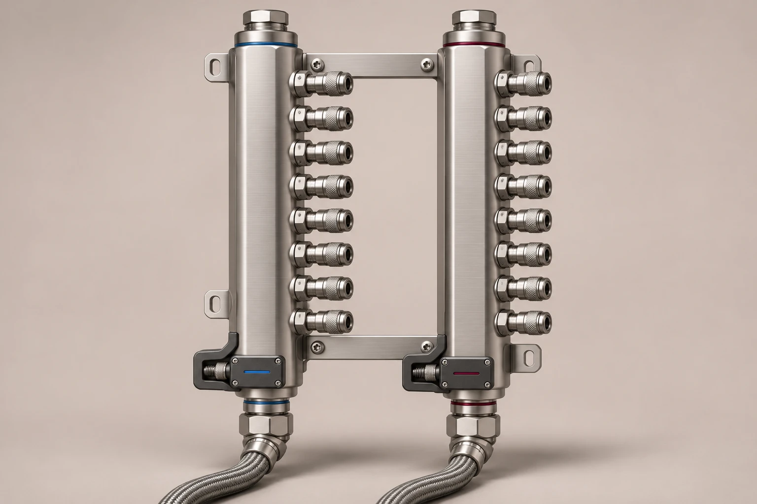
Each tray connects to both headers. Coolant can reach any tray without passing through another.
The manifold reports flow, temperature and pressure at the rack through the monitoring interface specified for the installation.
The controller adjusts the valves to meet the flow target. Calculating thermal power also requires supply and return temperatures and the coolant mixture.
The supply header brings coolant from the cooling system to the trays. The return header collects coolant after it has passed through the cold plates. Each tray has its own supply and return connection.
The branches run in parallel. Coolant does not have to pass through one server tray before reaching the next. That makes the manifold the shared connection between the rack and the rest of the liquid-cooling loop.
The manifold distributes and measures coolant at the rack. The connected cooling system supplies circulation and removes heat. Cold plates transfer heat from the chips into the coolant.
Rack-level sensing gives the rack a local reference. Total flow alone does not confirm the flow through each tray. The tray requirements and the branch checks remain part of the overall cooling design.
Manifold questions
Keep the assembly boundary, branch paths and measurements clear.
The manifold distributes coolant across multiple parallel branches and brings sensing and automatic flow control into the rack assembly. The Automatic Flow Valve is a standalone component for controlling a defined circuit. They can be specified together or separately.
Yes. Each connected tray has a separate supply and return branch. The branches share the headers. Rack total flow alone does not verify the flow through every tray; branch checks remain part of the system design.
Measured flow, supply and return temperatures and the confirmed fluid properties support a thermal power calculation. Integrating valid thermal power over time gives thermal energy. Glycol compensation uses the confirmed coolant profile; it does not change the blend or imply automatic concentration detection.
No. The manifold distributes and monitors coolant at the rack. The connected cooling system provides circulation and heat rejection. Its operating envelope and the tray requirements define the conditions the manifold must work within.
Confirm the branch layout, connector types, coolant compatibility, pressure and temperature limits, sensor positions, flow-control target, telemetry interfaces, override and fault behaviour. Agree verification and acceptance criteria for the actual assembly.
Start with the tray requirements. Check the physical connections, coolant and hydraulic conditions before agreeing the assembly.
Read the product brief and use the specification guide to define the requirements for your rack.