FluidSensing

Rack integration

Make the manifold fit the rack.

The manifold sits between the cooling loop and the server trays. Good integration starts with the rack layout, the tray requirements and a clear hydraulic boundary.
Explore the details
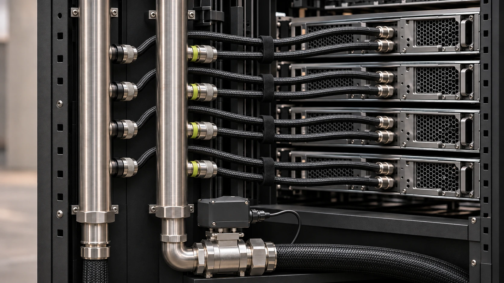
Manifold headers, braided hoses, a valve actuator and server trays inside a rack.

Start with the space around the trays.

Place the headers where the connections can be reached and the hoses can follow their permitted bend radius. Check the rack rails, tray travel, doors, cable paths and service access together.

Count the supply and return connections for the planned tray configuration. Include any approved future configuration in the port and hydraulic review. An unused connection must be closed using the specified method.

Check the interfaces together.

The fluid

Agree coolant chemistry, wetted materials, seals and cleanliness requirements.

The hydraulics

Match tray flow requirements and pressure losses to the available cooling supply.

The connection

Confirm coupling size, mating parts, hose length, routing and access.

The controls

Define power, commands, feedback, units, timestamps and failure behaviour.

Make the handover useful.

An installation record should connect the final rack layout to the engineering drawings, component specifications and acceptance results. Keep the sensing locations and units with the readings.

Record the installed tray configuration and relevant operating conditions when establishing a baseline. A later tray change can then be compared with a known starting point.

Use the specification guide

Common questions

Will one manifold fit every rack?

Rack dimensions, port arrangements, tray requirements and cooling interfaces differ. Confirm the mechanical and hydraulic fit for the intended configuration.

Can I choose the manifold from heat load alone?

Heat load matters, but it is not enough on its own. The fluid, tray requirements, available pressure, pressure losses, connectors and operating conditions also need to be reviewed.

What should be agreed before installation?

Confirm the drawings, coolant and material compatibility, operating limits, connection parts, sensor requirements, actuator interfaces and acceptance procedure.

Product details and rack requirements.

Read the product brief and use the specification guide to define the requirements for your rack.

FluidSensing product brief

Smart coolant manifold for liquid-cooled server racks

The smart rack manifold

FluidSensing brings supply and return distribution, rack-level sensing and integrated valve control into one assembly. Its control architecture is designed around measured flow, automated valve response and glycol compensation.

The coolant path

The supply header feeds server trays through separate parallel branches. Each branch passes through a tray's cold plates and returns to the return header. The headers connect only through those tray loops. Capped ports carry no coolant. The connected CDU or cooling system removes the heat.

Flow management and automated control

The intended feedback loop compares measured rack flow with an agreed flow target, adjusts the control valve and measures again. Valve position is a command or actuator-feedback value, never a substitute for measured flow. Supply and return temperatures add thermal context; pressure measurements describe the hydraulic conditions at defined points.

Glycol compensation

Use the confirmed fluid type, concentration and concentration basis, together with temperature-dependent fluid properties. Measured flow and paired supply and return temperatures support a fluid-aware thermal estimate. Any correction of the flow measurement depends on the selected sensor and its calibration. Automatic concentration detection is a separate sensing capability.

At the rack

Commission against an agreed flow target and operating envelope. Compare readings after trays or hoses change. A rack total cannot establish flow in every tray, and rack-level control does not imply individual branch actuation or balancing.

Engineering specification

Confirm the coolant, wetted materials, operating limits, sensor locations and calibration, control logic, actuator feedback, communication interface, override and loss-of-signal behaviour for the installation.