FluidSensing

Standalone flow control

Automatic flow valve.

Raise the flow target to lift the plug and let more coolant through.

Inside the flow valve

A modulating valve responds to a requested flow Coolant enters from the left, travels below the valve seat and passes through the opening to the right-hand outlet. The actuator lifts or lowers the plug, changing the opening. The moving streams show direction only, not measured flow. Actuator Coolant inlet Outlet Valve seat

A flow sensor measures how much coolant passes through.

One defined circuit

Control the opening.
Verify the flow.

A standalone valve for automatic flow regulation, temperature and pressure monitoring, and thermal power and energy monitoring using a configured glycol profile. In operation, measured flow closes the loop; valve position alone does not prove the flow.
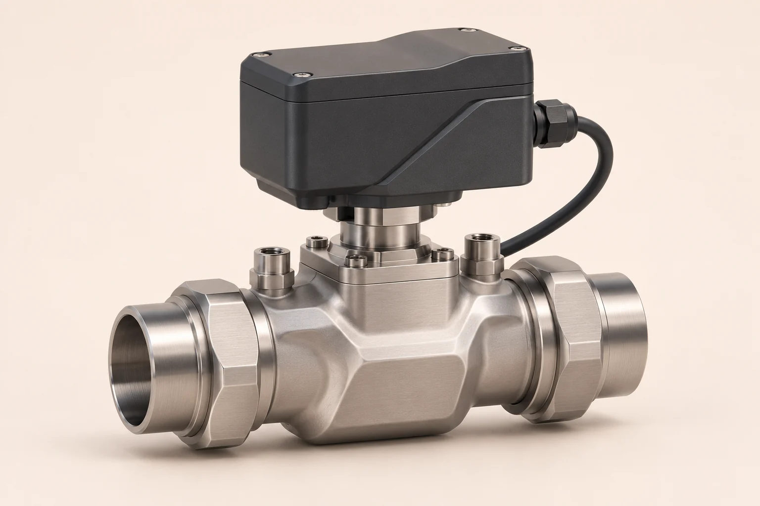
Standalone Automatic Flow Valve with an inline valve body and control module.
Standalone Automatic Flow Valve.

Regulate the circuit.

Compare the flow target with a measured response. Adjust the valve within the operating and control limits agreed for the application.

Read the conditions.

Keep flow, temperature and pressure with their measurement points. Telemetry provides the context for the connected control or monitoring system.

Account for the fluid.

Glycol type, concentration and temperature affect fluid properties. Use a confirmed profile when interpreting thermal power and energy.

Thermal context

From a flow reading
to a useful calculation.

Thermal power depends on more than flow. Combine volumetric flow with fluid density, heat capacity and the temperature rise across the defined load.

Measure
Flow, supply temperature and return temperature, with known locations, units and calibration.
Confirm
The coolant type, glycol concentration, whether concentration is by mass or volume, and the fluid-property reference.
Interpret
Apply the appropriate properties for the fluid and temperature. Integrate valid thermal power over time when thermal energy is required.

Glycol compensation keeps the fluid assumptions explicit. It does not change the coolant blend, automatically identify concentration or establish a sensor accuracy rating.

Valve questions

Clear signals.
Clear boundaries.

Define the controlled circuit and the measurements before choosing the component.

How is the valve different from the manifold?

The valve is a standalone component for automatic flow control in a defined circuit. The automatic manifold adds supply and return headers and multiple branch connections, with integrated monitoring and control.

Does a commanded valve position prove the flow?

No. The opening is a command or position signal. Actual flow also depends on the available pressure, the connected load and the rest of the circuit. Use the measured flow response as feedback.

What is needed to monitor thermal power and energy?

Use measured flow, supply and return temperatures at agreed points, and density and heat capacity for the confirmed fluid profile. Thermal power is approximately density × volumetric flow × heat capacity × temperature rise. Integrating valid thermal power over time gives thermal energy. Flow alone is not an energy measurement.

Does glycol compensation detect or change the concentration?

Not by itself. Compensation uses the confirmed glycol type, concentration basis and temperature-dependent properties in calculations. Automatic concentration detection is a separate sensing requirement. Flow-meter correction depends on the sensor, calibration and coolant.

Does the valve create circulation or replace the cooling system?

No. It regulates flow within the hydraulic conditions provided by the cooling system. Confirm the available pressure, circuit losses and required flow together.

What needs to be agreed before selection?

Confirm the controlled circuit, coolant profile, flow target, sensor positions, pressure and temperature limits, connection arrangement, actuator and telemetry interfaces, override and fault response. Validate the arrangement against the connected equipment requirements.

Start with your valve application.

Tell us about the controlled circuit, connected load and coolant. We can work through the sensing, interfaces and control requirements.

Need the distribution headers too?

Explore the automatic manifold for parallel supply and return distribution, local monitoring and integrated control at the rack.

FluidSensing product brief

Smart coolant manifold for liquid-cooled server racks

The smart rack manifold

FluidSensing brings supply and return distribution, rack-level sensing and integrated valve control into one assembly. Its control architecture is designed around measured flow, automated valve response and glycol compensation.

The coolant path

The supply header feeds server trays through separate parallel branches. Each branch passes through a tray's cold plates and returns to the return header. The headers connect only through those tray loops. Capped ports carry no coolant. The connected CDU or cooling system removes the heat.

Flow management and automated control

The intended feedback loop compares measured rack flow with an agreed flow target, adjusts the control valve and measures again. Valve position is a command or actuator-feedback value, never a substitute for measured flow. Supply and return temperatures add thermal context; pressure measurements describe the hydraulic conditions at defined points.

Glycol compensation

Use the confirmed fluid type, concentration and concentration basis, together with temperature-dependent fluid properties. Measured flow and paired supply and return temperatures support a fluid-aware thermal estimate. Any correction of the flow measurement depends on the selected sensor and its calibration. Automatic concentration detection is a separate sensing capability.

At the rack

Commission against an agreed flow target and operating envelope. Compare readings after trays or hoses change. A rack total cannot establish flow in every tray, and rack-level control does not imply individual branch actuation or balancing.

Engineering specification

Confirm the coolant, wetted materials, operating limits, sensor locations and calibration, control logic, actuator feedback, communication interface, override and loss-of-signal behaviour for the installation.